> For the complete documentation index, see [llms.txt](https://docs.archisketch.com/llms.txt). Markdown versions of documentation pages are available by appending `.md` to page URLs; this page is available as [Markdown](https://docs.archisketch.com/guide/enterprise-en/parametric-library/modular.md).
# Parts Editor
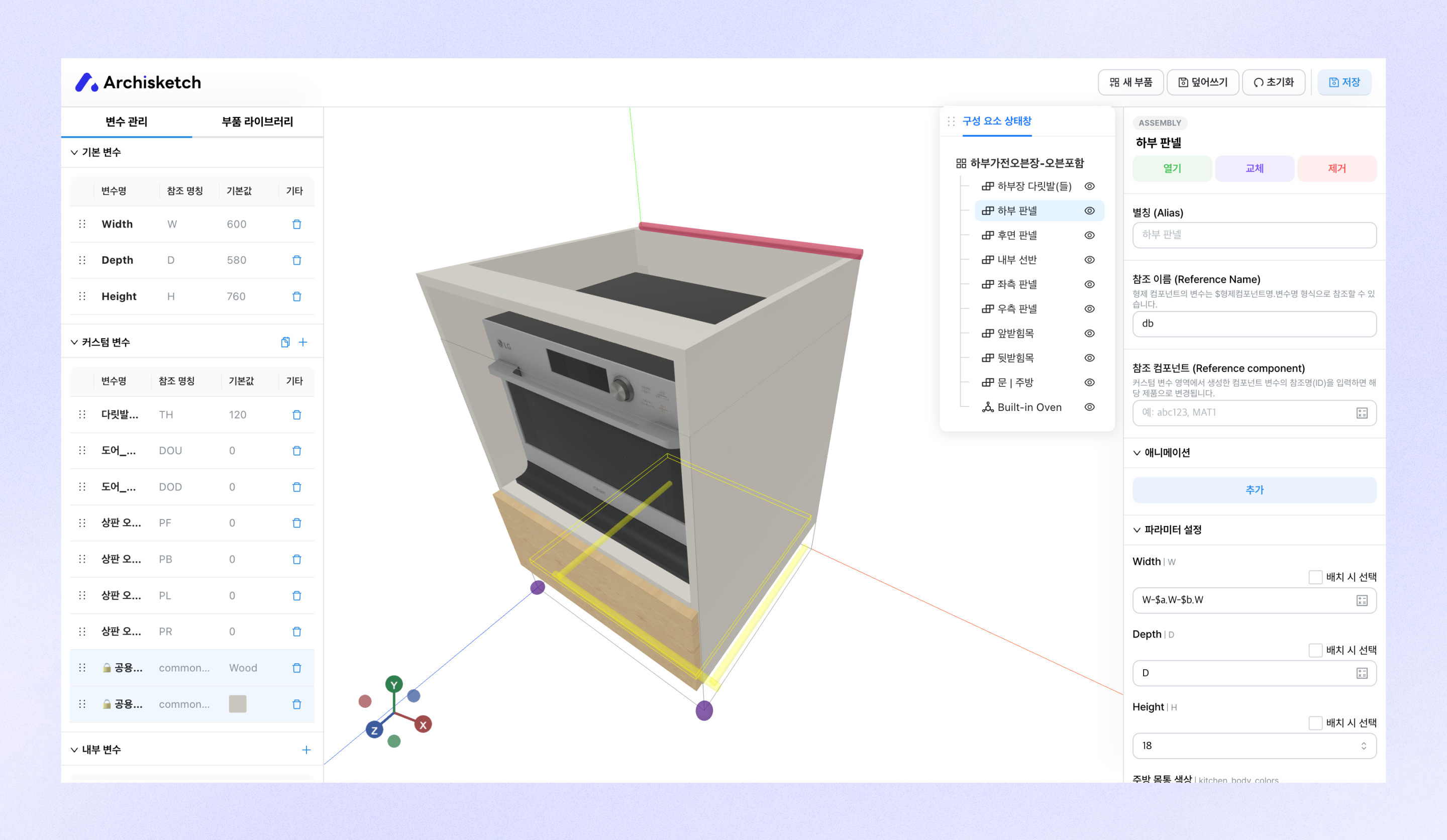
The part editor is an editor for creating and managing design parts available in the Archisketch editor.
## Enter Part Editor
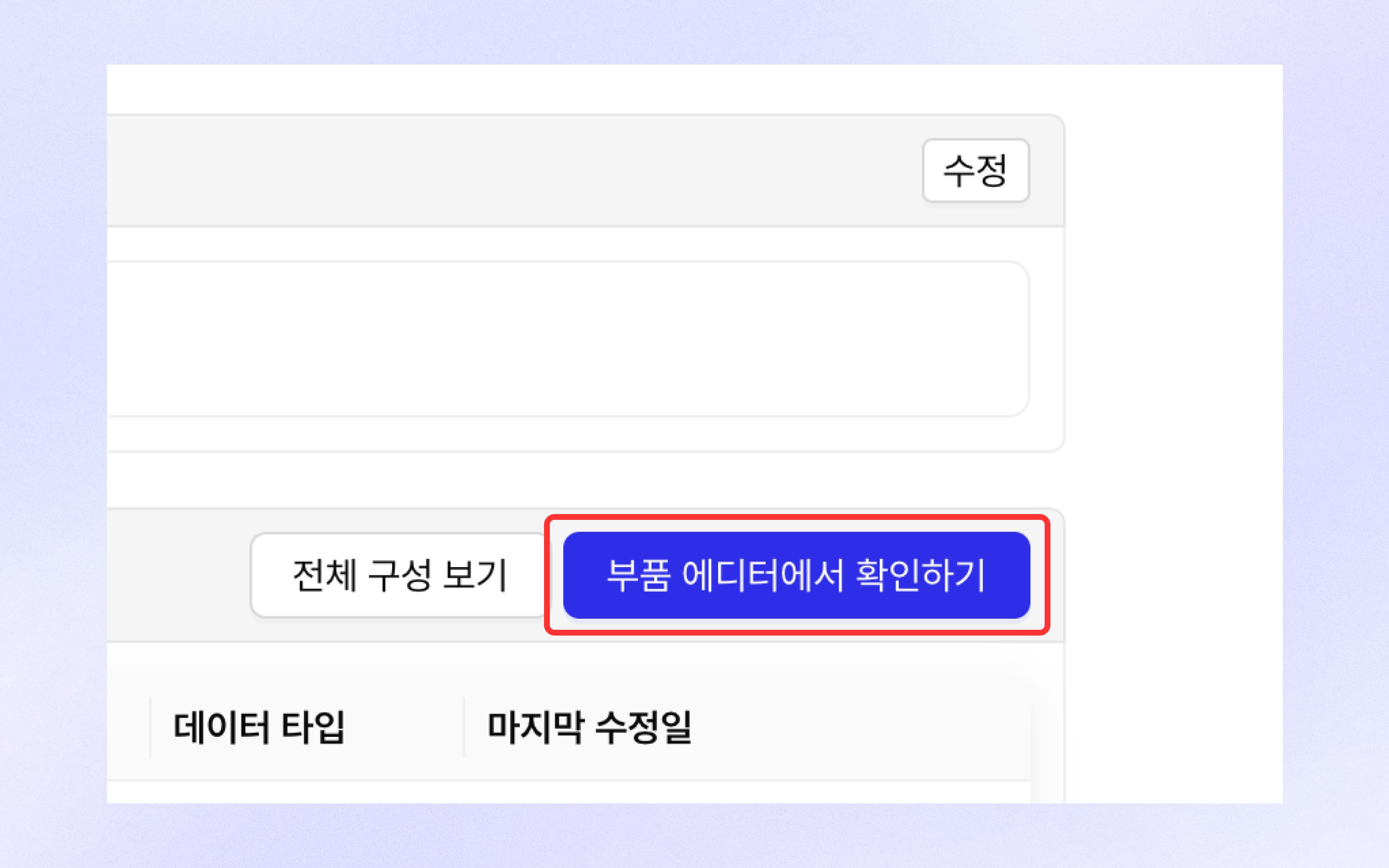
On the part details page, you can click the \[View in Part Editor] button to open that part in the part editor.
## Variables (Parameters)
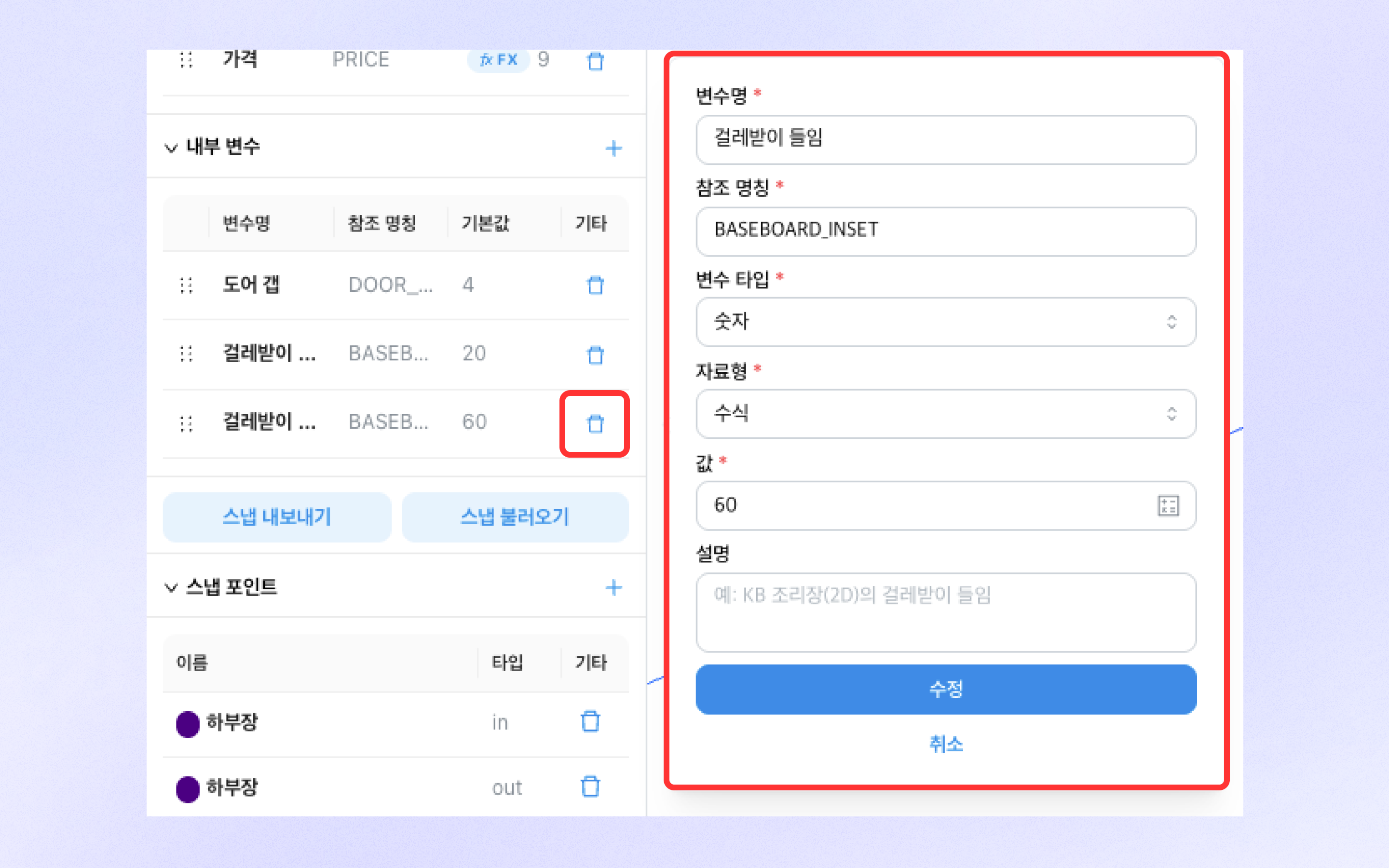
* The types of variables used to implement parametric parts are **1) basic variables, 2) custom variables, 3) internal variables** There are three types.
* When creating a variable, set the items below together.
* Variable name (a name for understanding its function and purpose)
* Reference name (a unique English name used when referring to the actual variable)
* Variable type (number, text, material)
* Data type (range, option, formula)
* Depending on each variable type and data type, related information such as option values and default values must be entered.
### Basic variables
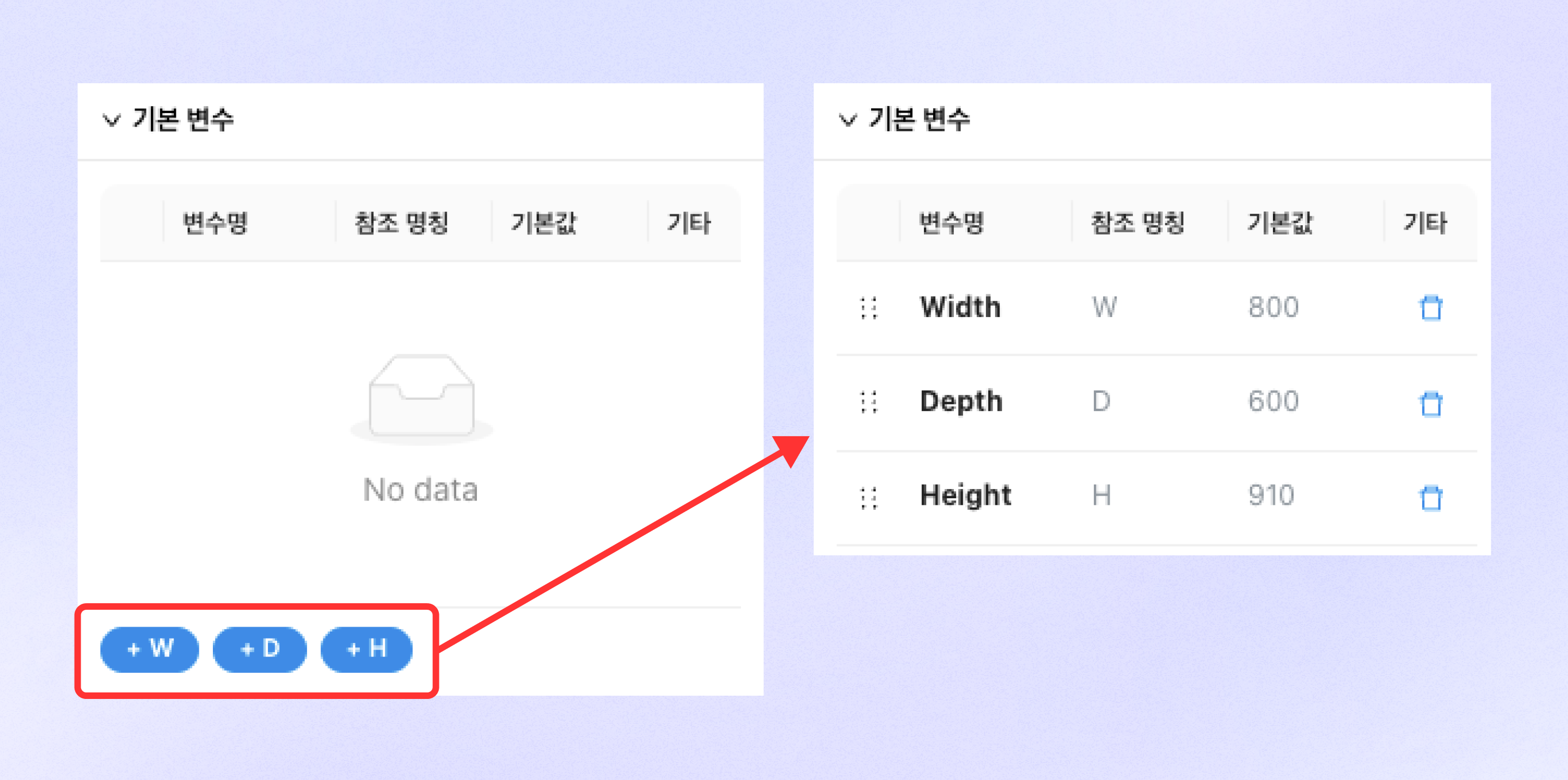
* Basic variables are variables that manage values corresponding to a part's width (W), depth (D), and height (H).
* You can add each variable by clicking the W, D, H buttons.
* The added basic variables can be changed by directly entering values in the editor and the part editor (other parts).
* You can delete a variable by clicking the trash button on the right side of the variable list.
### Custom variables
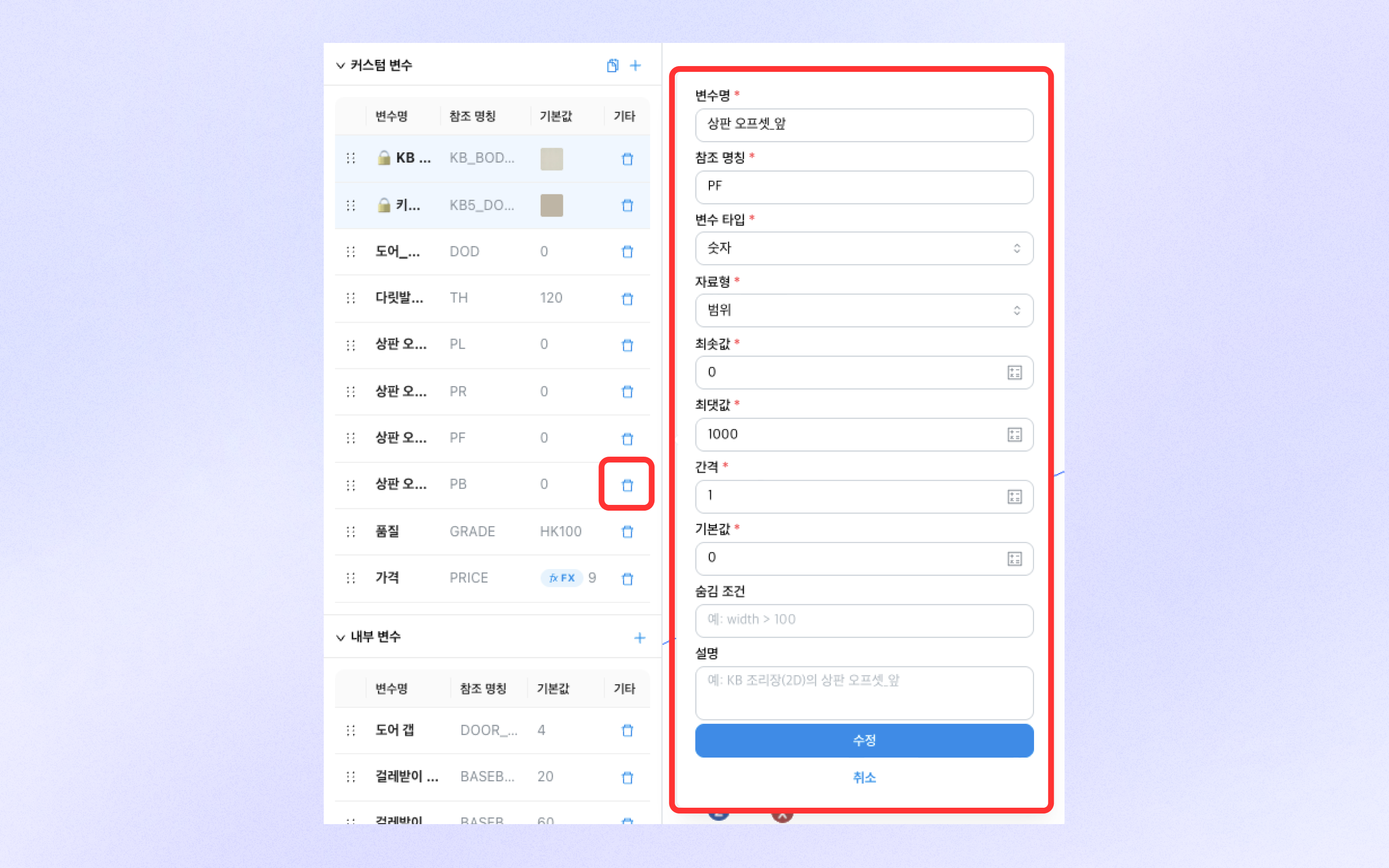
* Custom variables are variables that manage values that can be edited in the editor beyond basic variables.
* You can add custom variables by clicking the \[+] button at the top right of the section.
* You can add enterprise variables by clicking the file-shaped button to the left of the \[+] button.
* The added custom variables can be changed by directly entering values in the editor and the part editor (other parts).
* You can delete a variable by clicking the trash button on the right side of the variable list.
### Internal variables
* Internal variables are variables that manage values repeatedly used inside the part editor.
* You can add internal variables by clicking the \[+] button at the top right of the section.
* Internal variables cannot be changed by directly entering values in the editor and the part editor (other parts).
* You can delete a variable by clicking the trash button on the right side of the variable list.
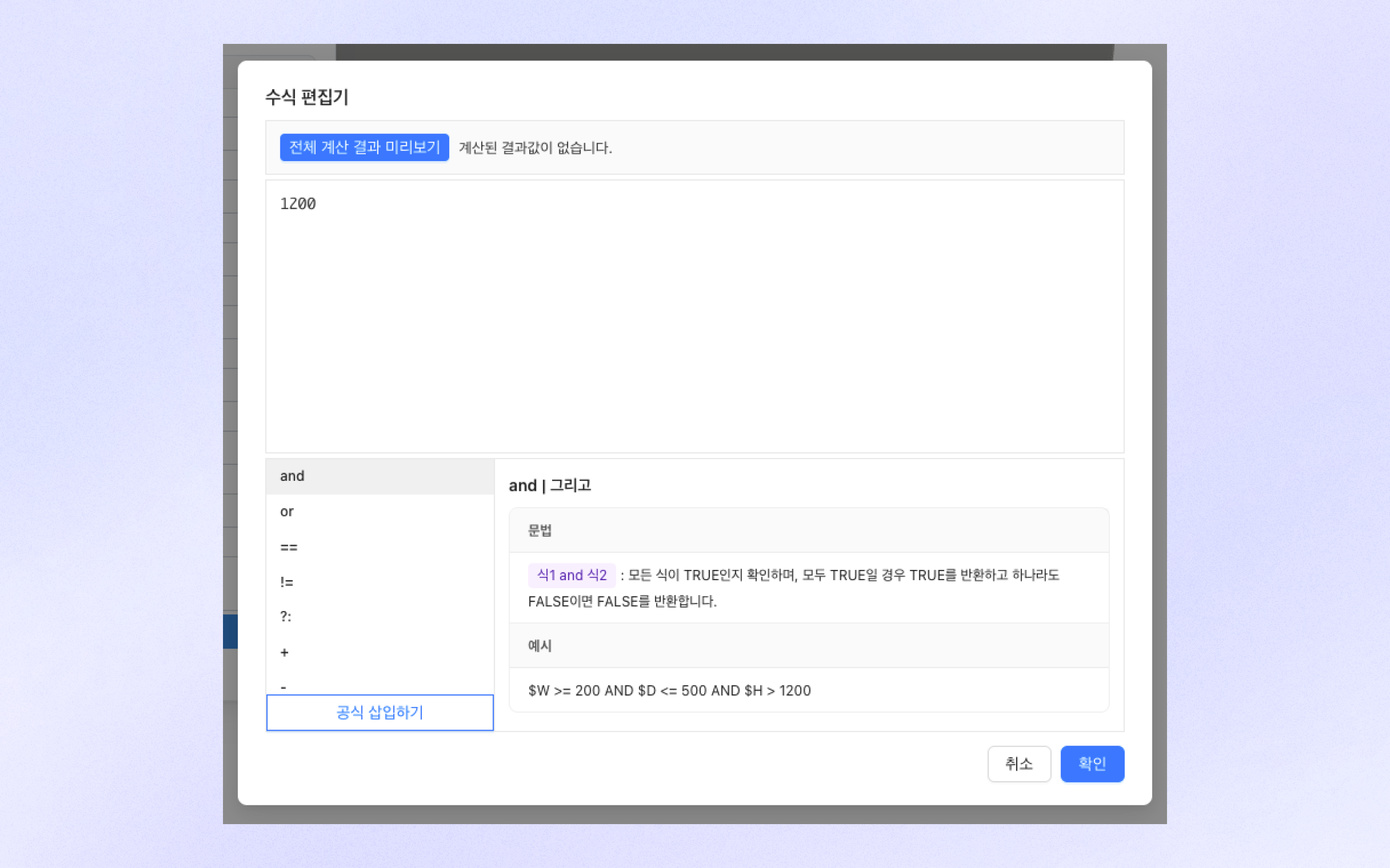
### Enter formula
* Formulas can be used in all fields where numbers are entered in the part editor.\
You can freely enter conditional expressions and transformed values using variables.
* Clicking the calculator button on the right side of the input field takes you to the formula editor, where formulas can be entered more conveniently.
* In the formula editor, you can use not only basic mathematical symbols, but also various advanced mathematical functions and string processing functions while checking explanations and examples.
* The formula you entered can be previewed at the top
You can preview the calculated result through the 'Preview all calculation results' button.
## Snap
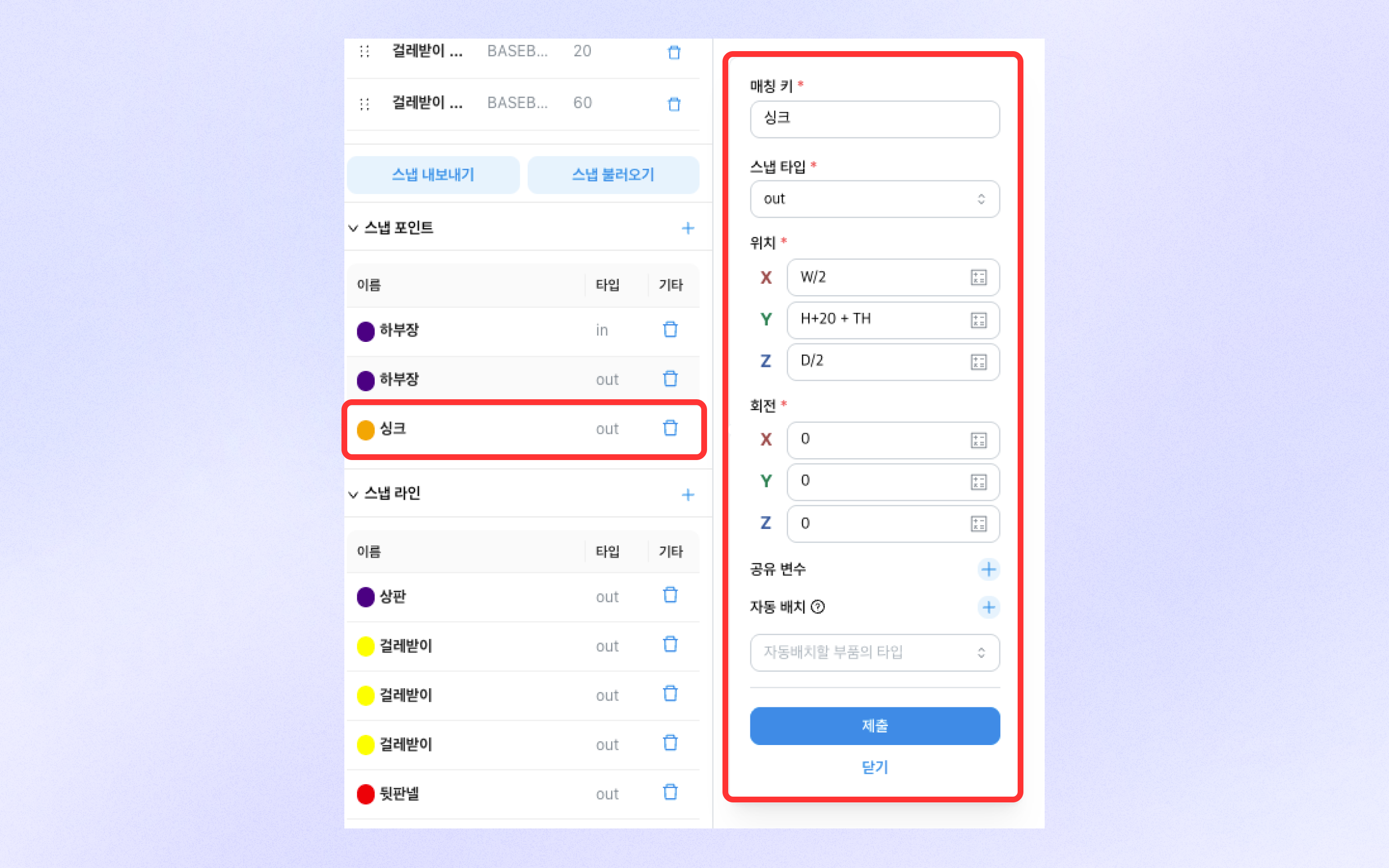
### Snap point
* A snap point is a feature that allows products to be connected to each other with snaps in the editor based on points.
* You can add a snap point by clicking the \[+] button at the top right of the section.
* In the editor, snap **1) when the matching key is the same, and 2) when the snap type is different** works.
* When shared variables are set, other products connected by snap will share the same variable values.
* When automatic placement settings are used, the corresponding part is automatically placed on the snap when the finishing automatic placement feature is used.
* You can delete a snap point by clicking the trash button on the right side of the snap point list.
* Snap points are shown in the part editor as dots in a fixed color.
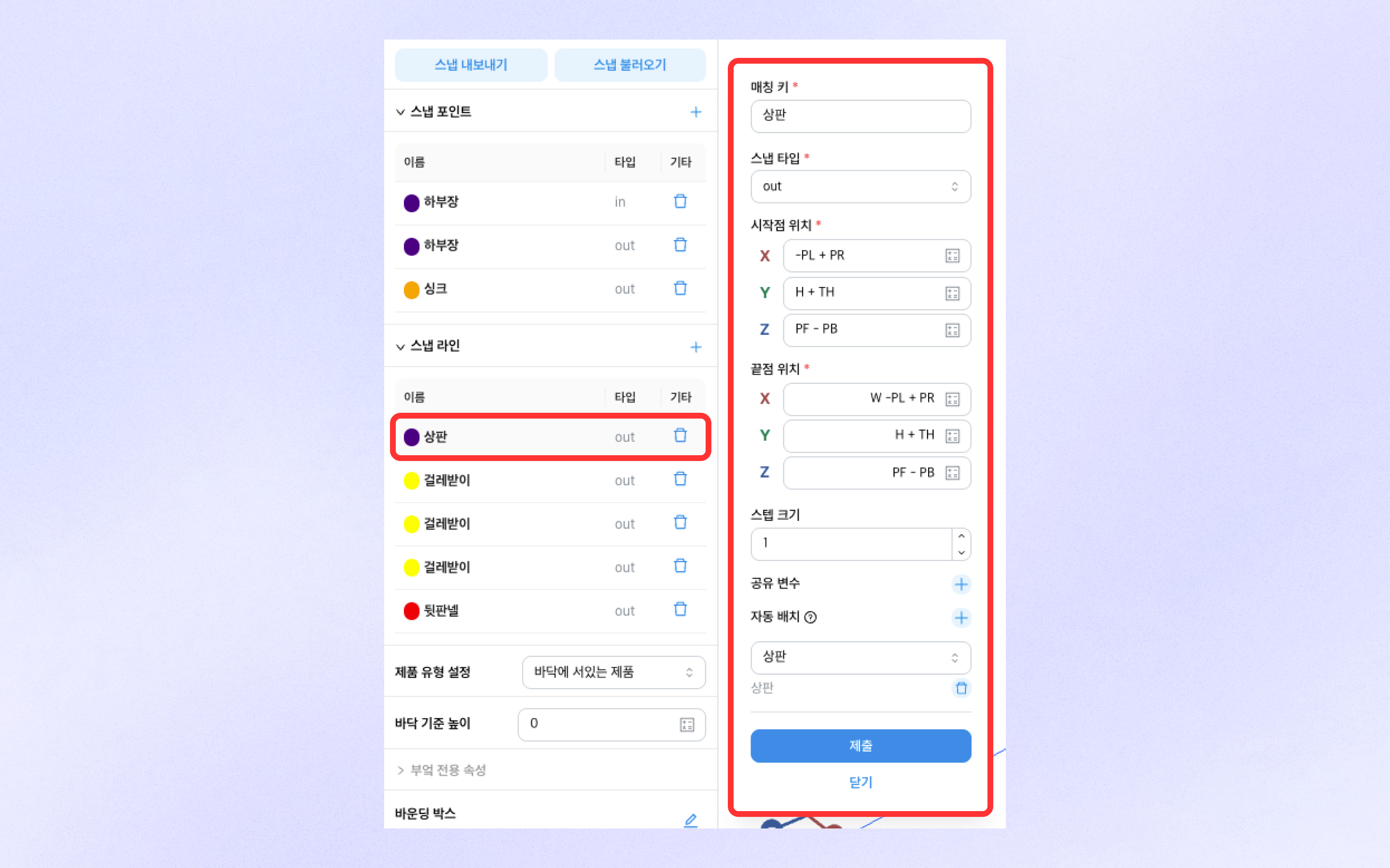
### Snap line
* A snap line is a feature that allows products to be connected to each other with snaps in the editor based on lines.
* You can add a snap line by clicking the \[+] button at the top right of the section.
* In the editor, snap 1**) when the matching key is the same, and 2) when the snap type is different** works.
* Snap lines connect starting points to starting points and end points to end points.
* When shared variables are set, other products connected by snap will share the same variable values.
* When automatic placement settings are used, the corresponding part is automatically placed on the snap when the finishing automatic placement feature is used.
* You can delete a snap point by clicking the trash button on the right side of the snap point list.
* Snap lines are shown in the part editor as lines in a fixed color.
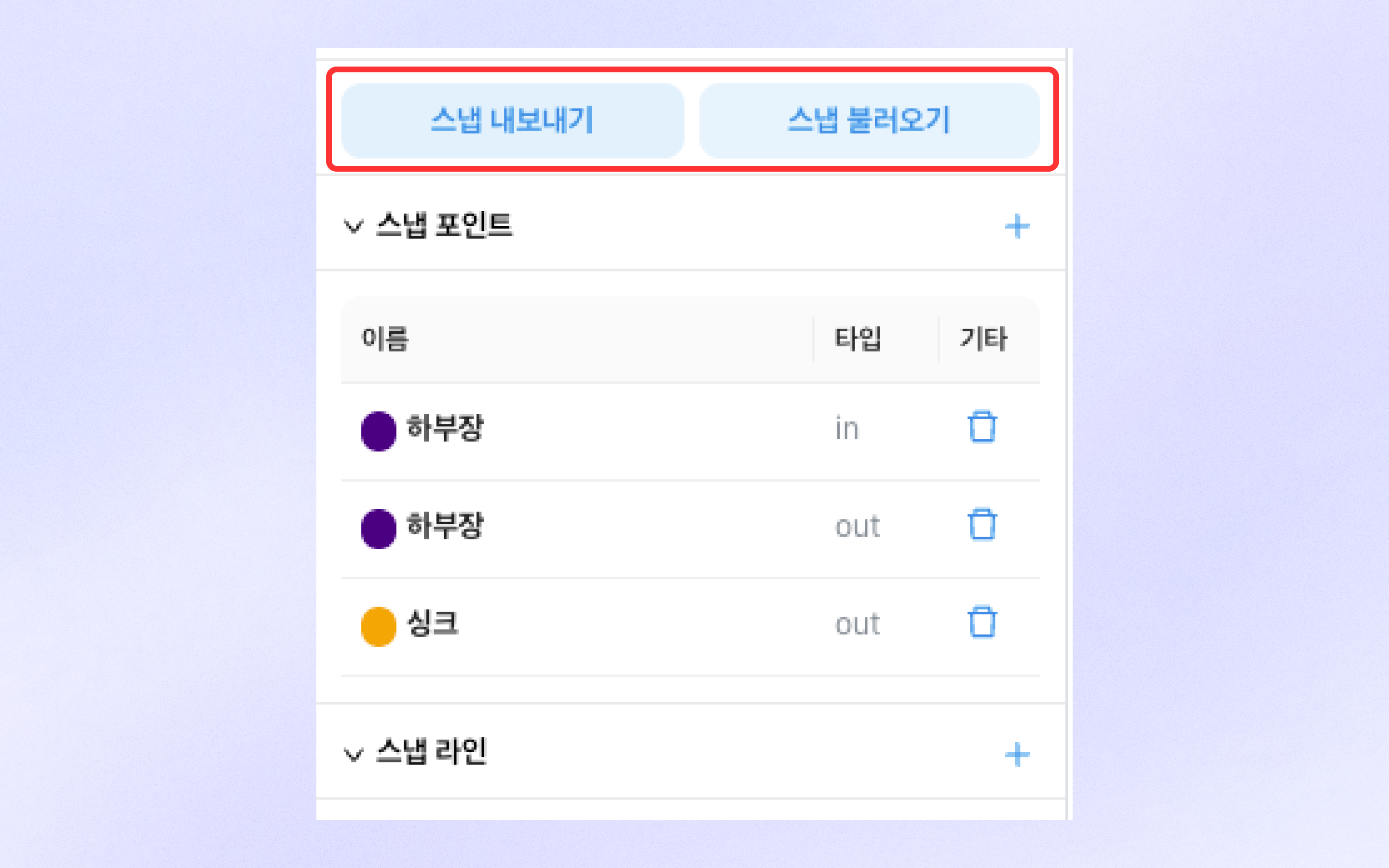
### Export & Import Snap
* Export & Import Snap is a feature that can apply another part's complex snap settings as they are.
* When you click \[Export Snap], the snap information is copied to the clipboard in JSON format.
* If you click 'Import Snap' in the part you want to import while the snap information is copied, the snap information will be applied.
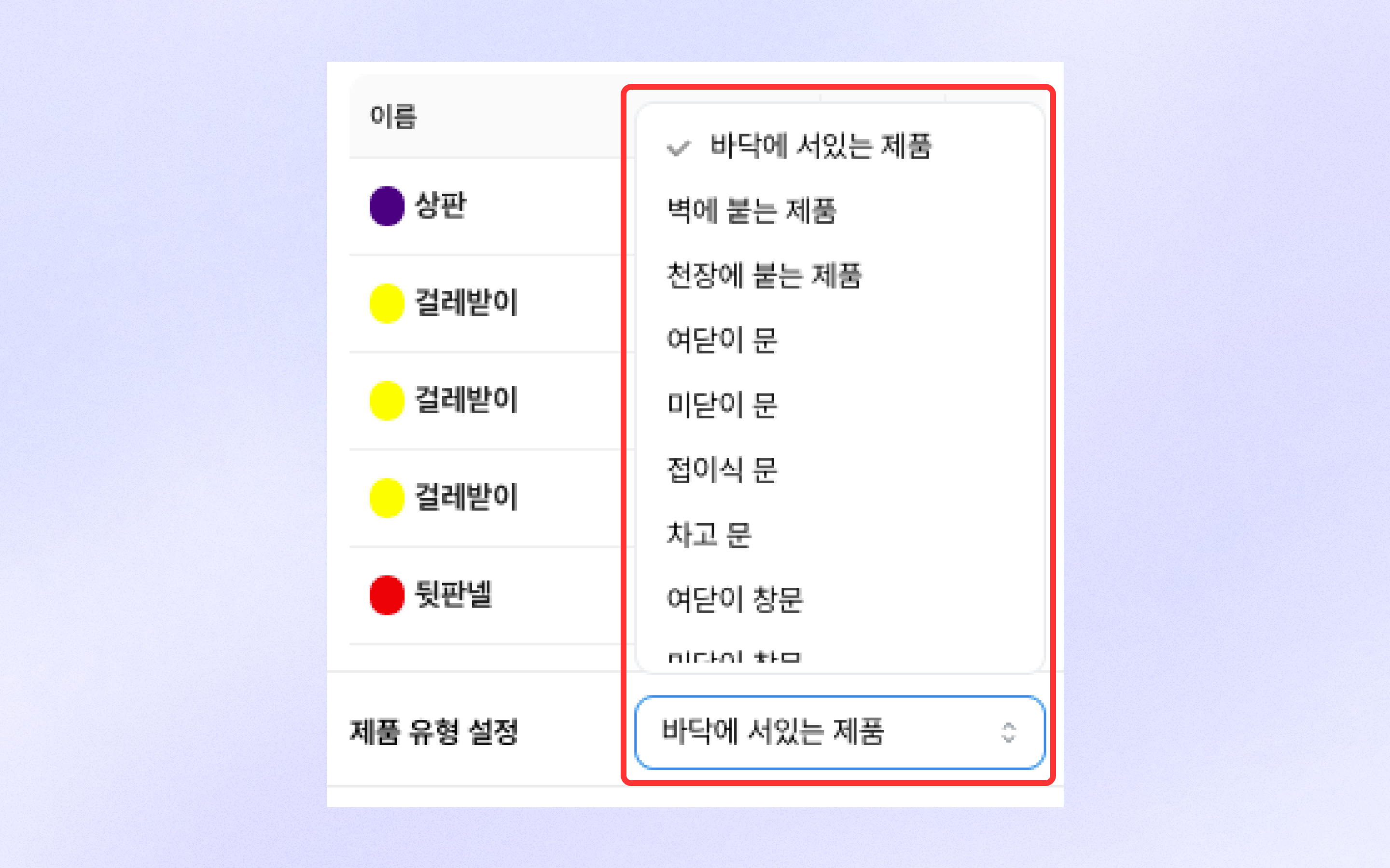
## Product type settings
* You can select the product type in product type settings.
* In the case of a 'wall-mounted product', it is automatically set to be placed only on walls in the editor.
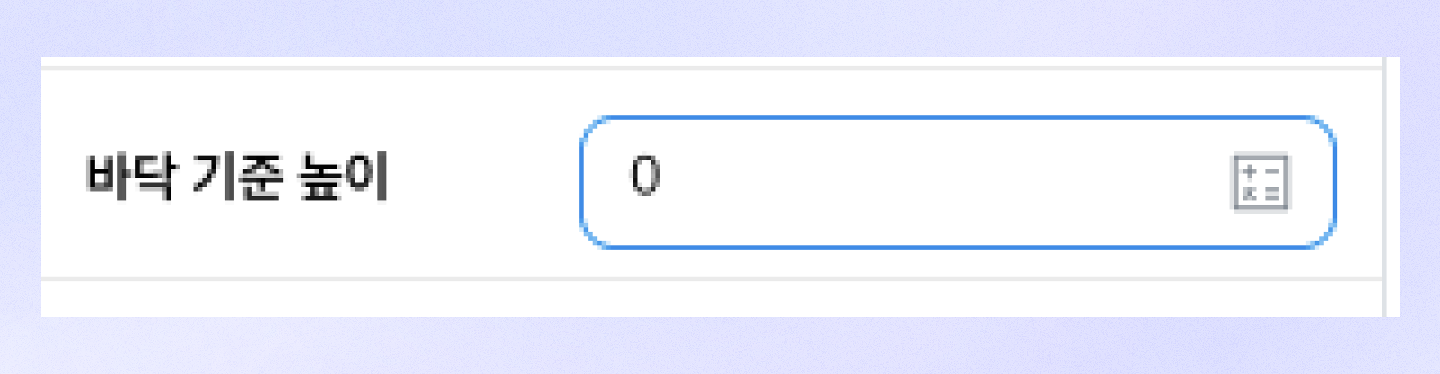
## Floor-based height settings
* When floor-based height is set, the item is placed in the editor elevated from the floor by that height.
* Floor-based height can also be set using variables.
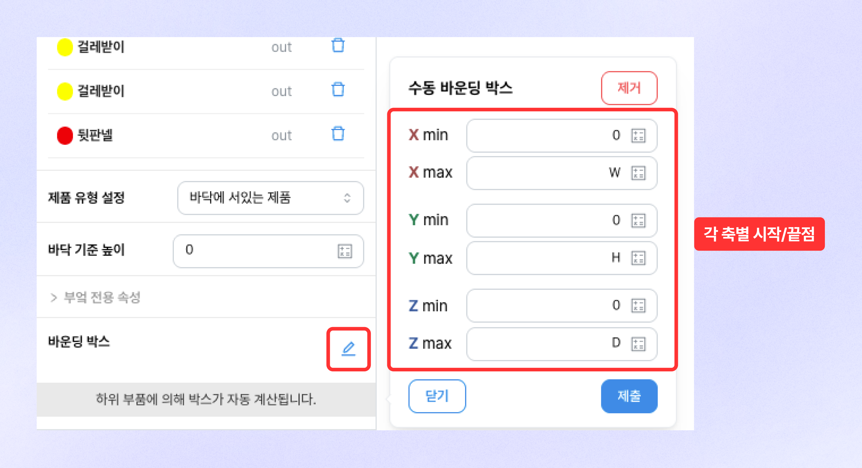
## Bounding box
* A bounding box refers to the 기준 for measuring a product's size as shown numerically in the editor.
* By default, the bounding box is automatically set based on a rectangular prism enclosing the outermost boundaries of the part.
* You can manually set the bounding box by clicking the edit button on the right side of the section.
* When setting a manual bounding box, you can set a size standard separate from the visible size.
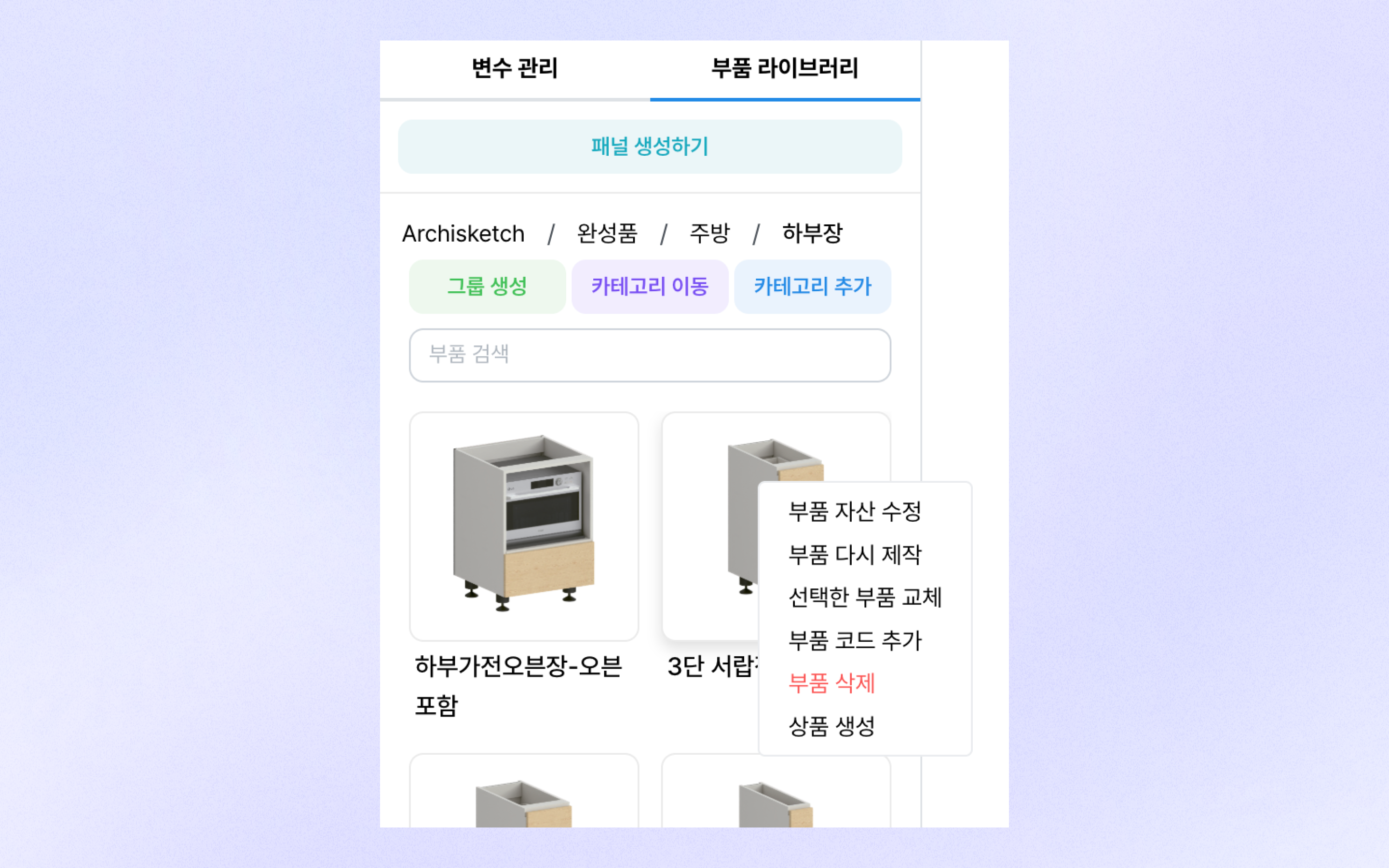
## Part Library tab
1\. You can select the parts to bring into the part editor from the part library.
2\. You can enter the Part Library tab by clicking 'Part Library' at the top left.
3\. Clicking a part thumbnail adds the selected part to the part editor.
## Part management
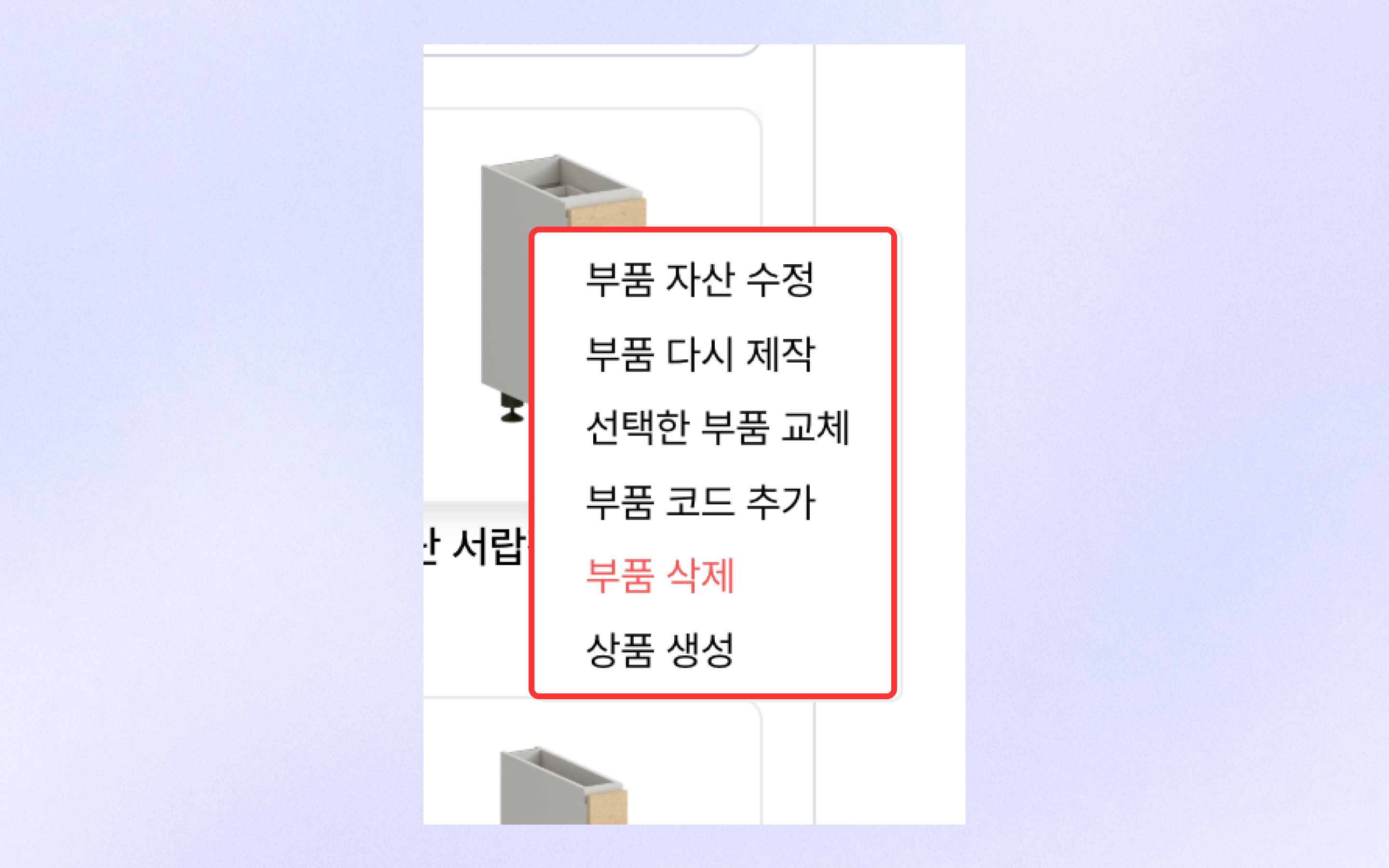
* Part thumbnail **Right-clicking the mouse**displays additional part functions.
* **\[Edit Part Asset]** Click to edit the part thumbnail.
* **\[Rebuild Part]** Clicking opens the part in a new part editor tab.
* **\[Replace Selected Part]** Clicking replaces the selected part in the part editor with that part.
* **\[Add Part Code]** Clicking the button opens the add part code modal.
* **\[Delete Part]** Clicking deletes the corresponding part from the part library.
* **\[Create Product]** Clicking creates a product that references the corresponding part.
## Part information
### Alias, reference name, reference component
* An alias is a naming feature used to distinguish parts within the component state window inside that part.
* The reference name is the name used to refer to the variable value of that function in other parts.
* If you enter the reference name of a component type added in custom variables for the reference component,\
the modeling changes according to the variable values of that component type.
### Animation
* If opening and closing motions such as doors and drawers are needed, they can be set through the animation feature.
* You can quickly apply animations by type by clicking buttons such as DoorL and DoorR at the top.
### Parameter settings, position, rotation
* Parameter settings are a feature that allows you to set the basic and custom variable values of the corresponding part.
* If you select 'Select on placement' in parameter settings, you can change that parameter in placement mode.
* Position and rotation are features that allow you to set the position and rotation values based on the part's coordinate axes.
### Symmetry flip
* Symmetry flip is a feature that allows you to flip the corresponding part based on each axis.
* Even if flipped, the position reference remains fixed at the same location.
### Hide conditions
* The hide condition feature hides the corresponding part in the editor according to specific conditions.
* Conditions can be set through equations or inequalities based on variable values.
### Thickness (panel)
* Shown only for panel parts, and allows you to adjust the panel thickness.
## Panel
A panel is an object (part) whose shape and thickness can be freely edited point by point.
### Add panel
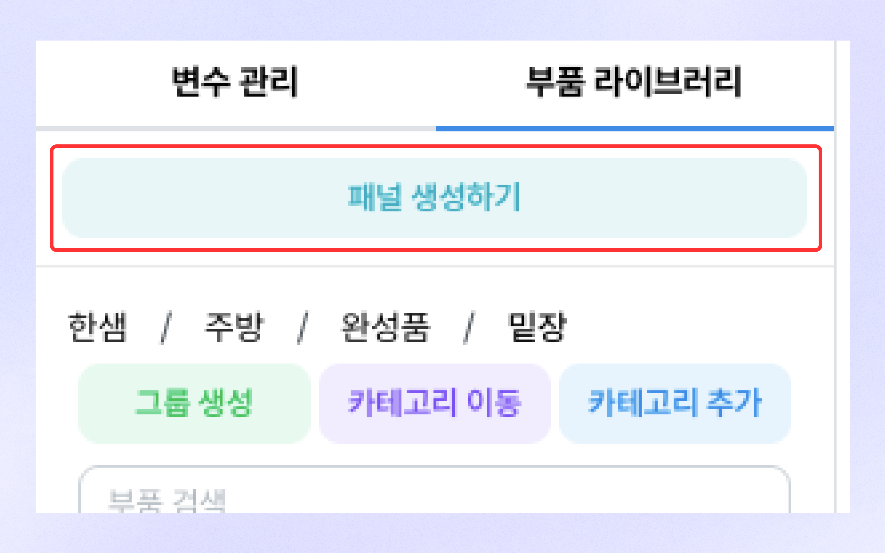
* Clicking \[Create Panel] in the Part Library tab creates a rectangular panel in the part editor.
* The created panel can be modified in the panel shape editor.
### Panel editing (panel shape editor)
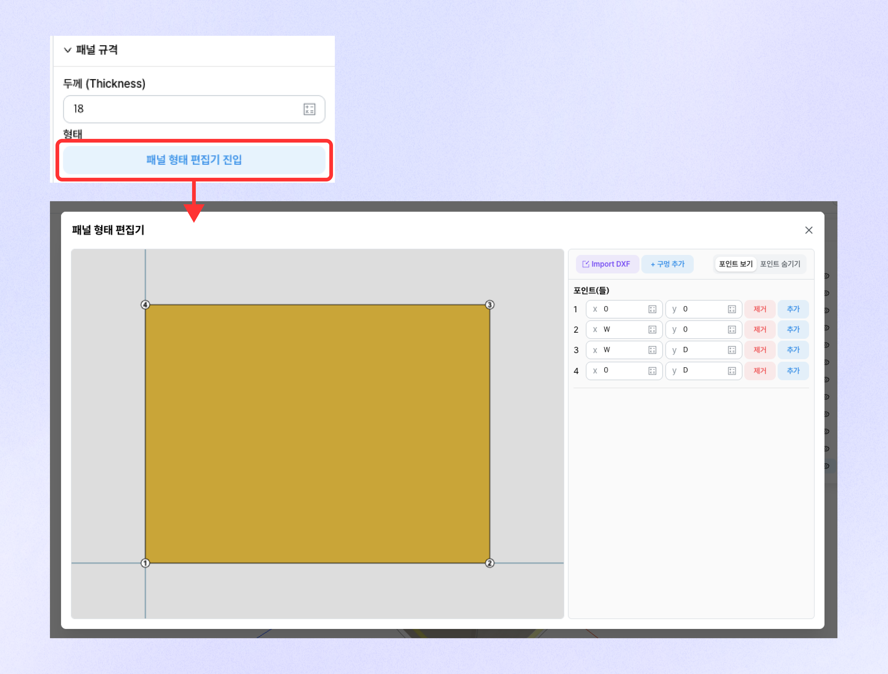
* After selecting a panel, you can enter by clicking the \[Enter Panel Shape Editor] button at the bottom right.
* In the panel shape editor, you can edit the panel shape based on each panel's points.
* You can remove the corresponding point or add a new point through the \[Remove] and \[Add] buttons on the right.
* Clicking the \[Import DXF] button lets you select a 2D DXF file and import the panel.
* When adding a hole, a rectangular hole that passes through the panel is created, and points can be managed for each hole.
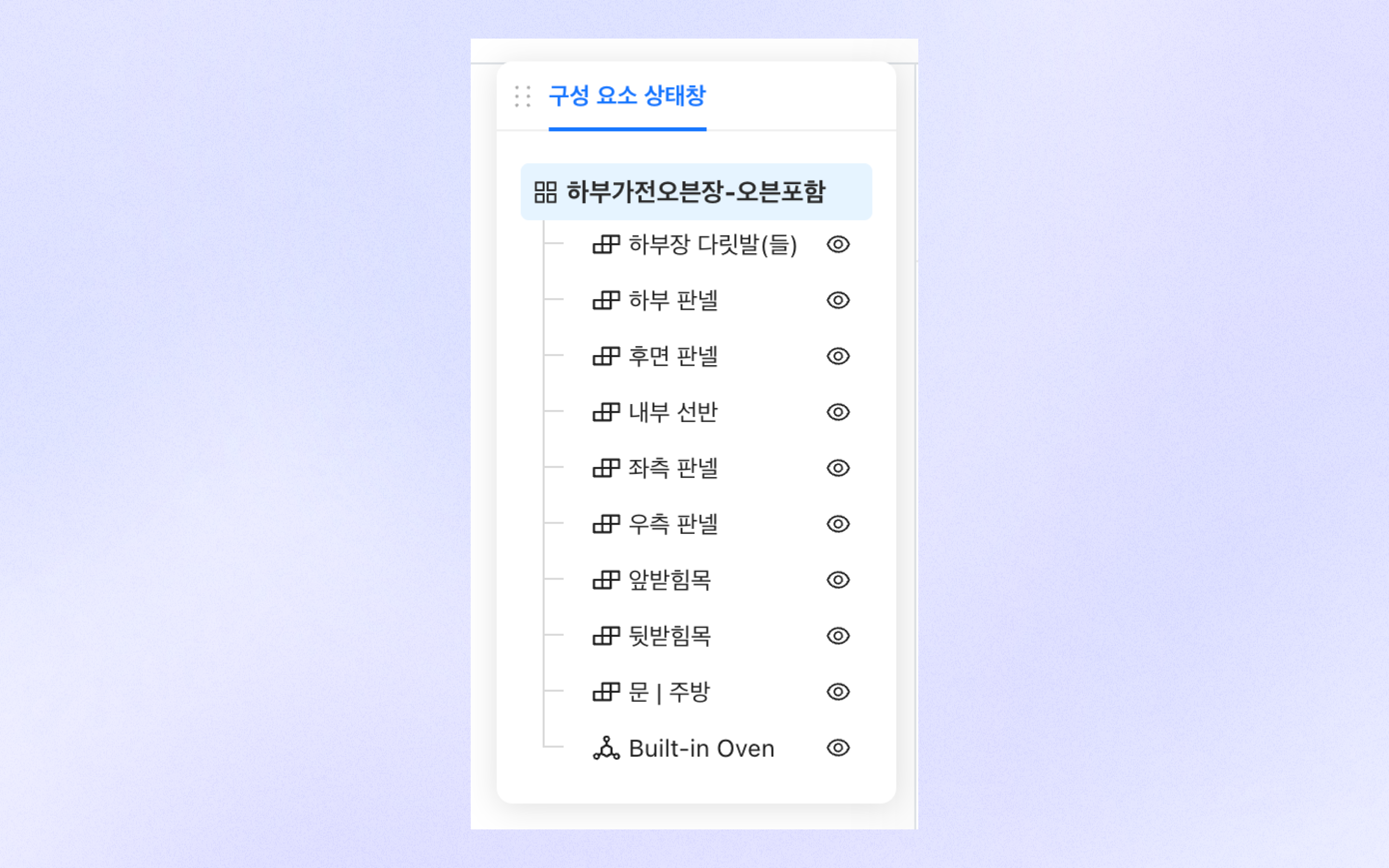
## Component state window
* In the component state window, you can check the child parts used in the corresponding part.
* You can hide a part through the eye icon on the right. (Hidden state is applied only in the part editor.)
## Part management
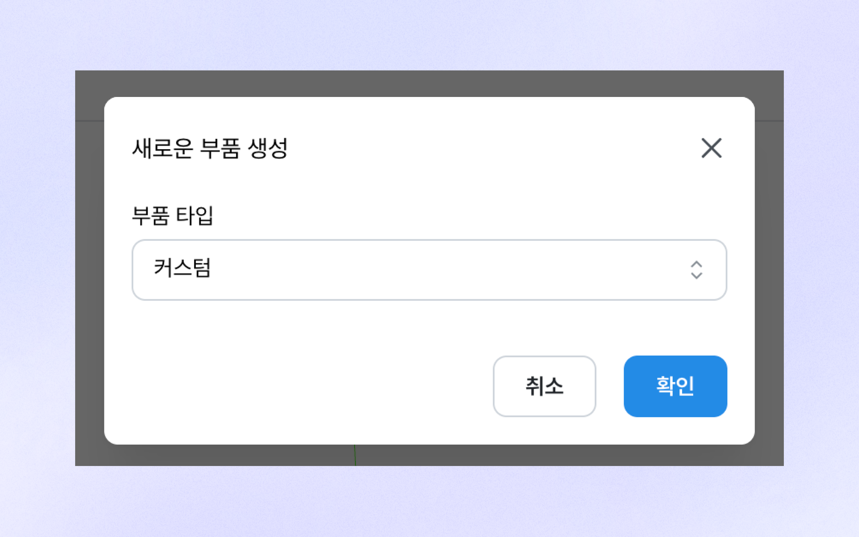
### Create new part
* Click \[New Part] in the header to create a new part.
* You can select the part type when creating a part.
* Clicking the \[Confirm] button takes you to the part editor screen for editing the new part.
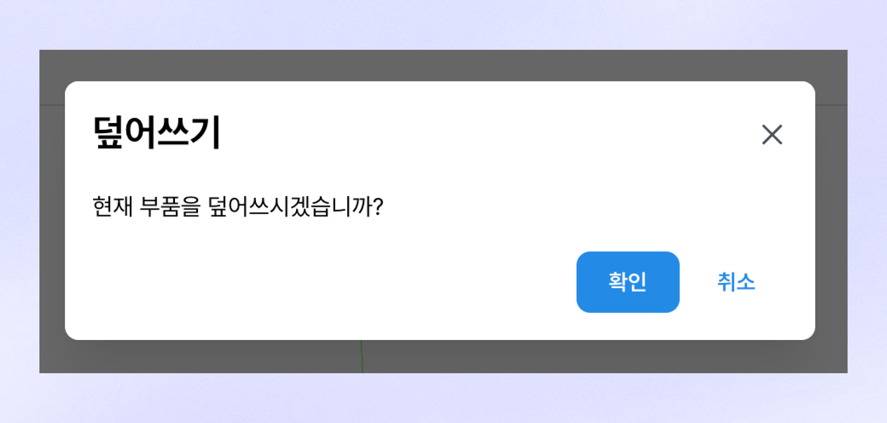
### Overwrite
* Click \[Overwrite] in the header to apply changes to the corresponding part.
* If you leave the part editor without overwriting, your changes may be lost.
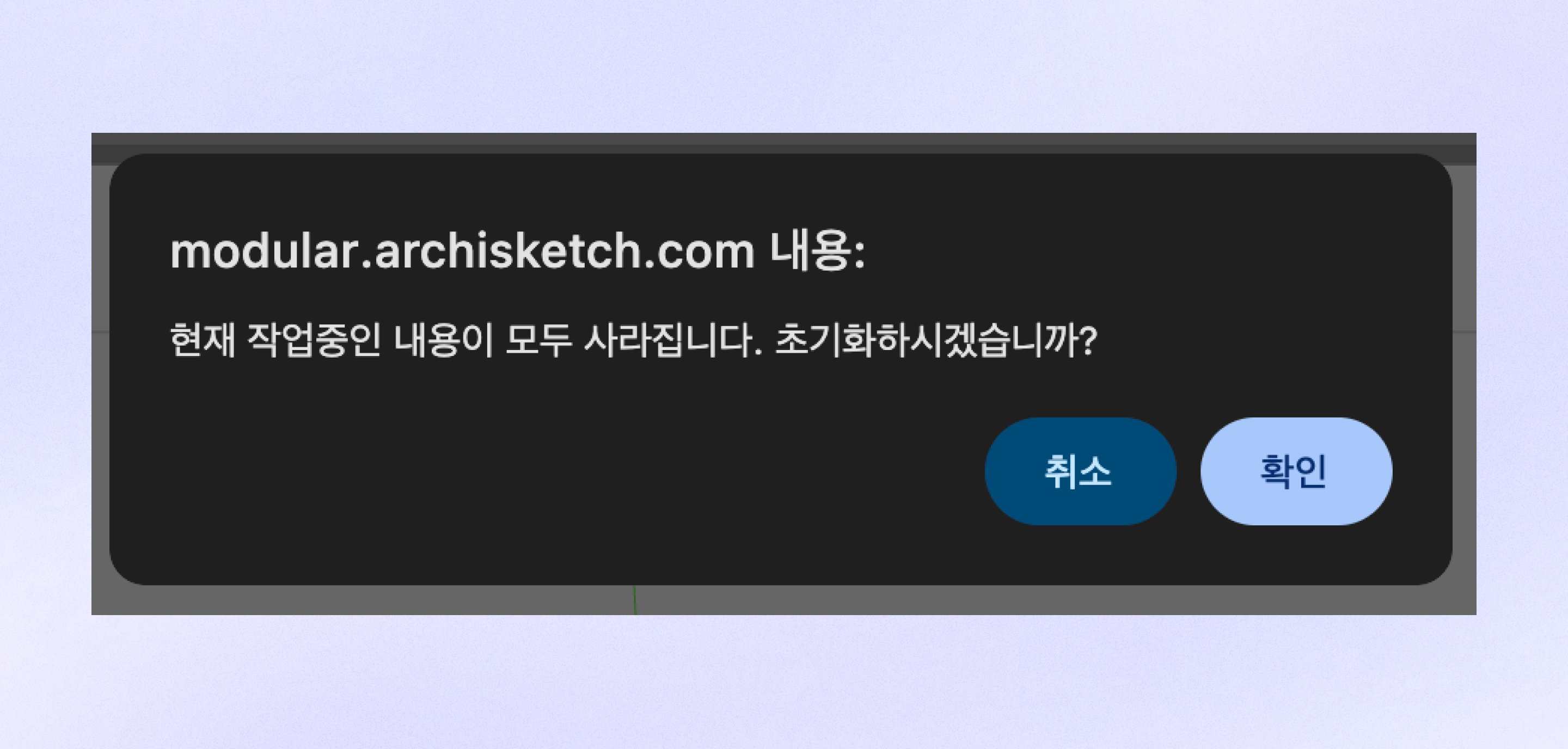
### Reset
* Clicking the \[Reset] button resets all current work.
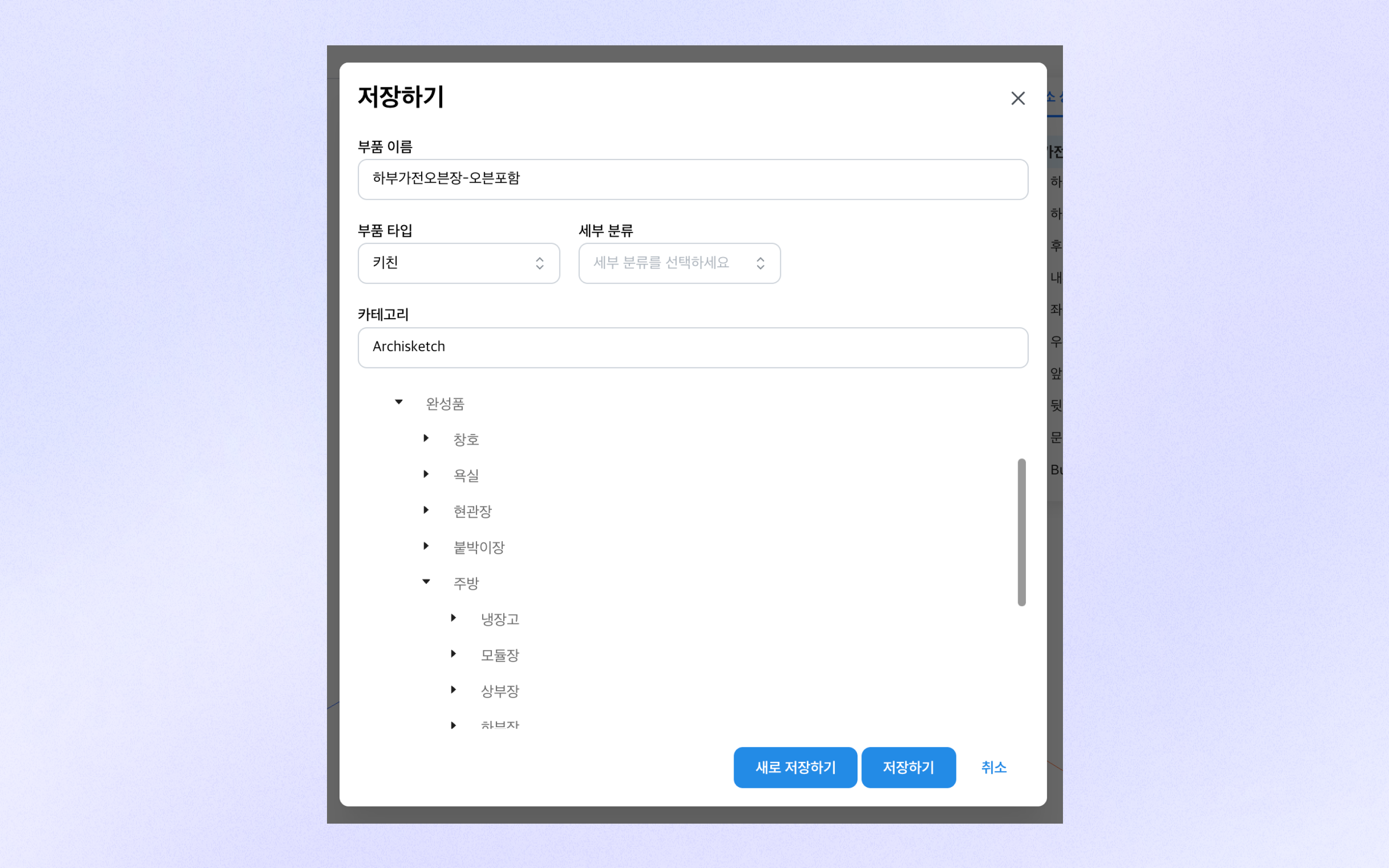
### Save
* Clicking the \[Save] button in the header opens the save modal.
* You can enter the part name and part type.
* If you select a category to save to, you can create/move the part to that category.
* Clicking \[Save as New] saves it by duplicating it as a new part.
---
# Agent Instructions
This documentation is published with GitBook. GitBook is the documentation platform designed so that both humans and AI agents can read, navigate, and reason over technical content effectively. Learn more at gitbook.com.
## Querying This Documentation
If you need additional information that is not directly available in this page, you can query the documentation dynamically by asking a question.
Perform an HTTP GET request on the current page URL with the `ask` query parameter, and the optional `goal` query parameter:
```
GET https://docs.archisketch.com/guide/enterprise-en/parametric-library/modular.md?ask=&goal=
```
`ask` is the immediate question: it should be specific, self-contained, and written in natural language.
`goal` is optional and describes the broader end goal you are ultimately trying to accomplish on behalf of the user. GitBook uses it to tailor the answer towards what is most useful for that goal.
The response will contain a direct answer to the question and relevant excerpts and sources from the documentation.
Use this mechanism when the answer is not explicitly present in the current page, you need clarification or additional context, or you want to retrieve related documentation sections.